Automated inspection of welds

The new weld check package in GOM Inspect Pro ensures automated and standardized inspections of welds. Together with the T-SCAN, selected scan data can be evaluated with maximum comfort.

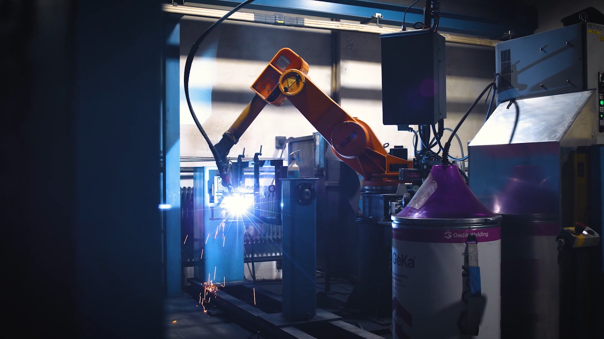
Automated welding processes have long been a reality in the production chain thanks to innovative industrial robots. The situation is quite different when it comes to quality assurance of the welds – manual inspection methods such as calipers and measuring tapes are still frequently used here. However, these inspection methods are difficult to automate and standardize. That is why Stahlotec GmbH and the experts from #HandsOnMetrology, our 3D scanning network, have developed the new “Weld Check” software function package. This enables automated inspection of welds in accordance with DIN EN ISO 5817. This is achieved by relying on 3D scanning and the GOM Inspect Pro inspection software.

Defective welds result in damaged parts or, in the worst case, the failure of entire weld structures. For safety reasons, some industries are therefore obligated to subject the welds to a regular safety inspection. Dynamically loaded welded structures, such as those found in rail vehicle construction, steel construction, pressure tank construction, road and railroad bridge construction and pipeline construction, are subject to mandatory inspection in accordance with DIN EN ISO 5817. The standard determines irregularities that may occur and assigns them to rating categories that correspond to different safety requirements.
One of the first and most important methods for external quality control of welds is the visual inspection by the weld inspector, also called visual testing (VT). It serves to identify obvious deviations in shape, dimensional accuracy and surface structure. These weld irregularities present a deviation from the desired quality degree of a product. Their formation is influenced by the base material, the welding process and the seam preparation. Frequent irregularities are, for example, cracks or pores, undercuts, an underarching of top layers or excessive weld reinforcement.

weld-check_robot_stahlotec

Previous procedure of visual testing of welds and its disadvantages

When looking at modern manufacturing processes and welding robots, the inspection of welds becomes a bottleneck in parts of the industry, as this is not yet automated. This is still done by staff, or more precisely: the weld inspector. Visual testing describes the exterior quality assurance of the weld. According to DIN EN 13018, it is based on the evaluation of the interaction between the medium light and the specimen. Therefore, the correct lighting conditions are elementary. 500Lx is recommended, which corresponds to standard interior lighting. However, test sites are not always brightly lit and welds are often located in hard-to-reach areas of the part. Thus, flashlights are a common tool. In addition, there is a range of manual measuring devices such as calipers, three-scale gauges, steel gauges and seam gauges. With these tools, numerous dimensions are taken and then compared with the permissibility criteria of the stipulated standard. In addition, the VT inspection also checks whether all welded joints correspond to the previous drawing specification in terms of position and completeness. The weld supervisor then decides whether any detected defects can be repaired or, in the worst case, whether the part must be scrapped.
The visual testing is very time consuming and work intensive. Particularly with large crafts and poorly accessible welds, careful inspection can only be ensured by spending a great deal of time. The missing digital documentation of the visual testing complicates a follow-up in case of defects occurring later. Due to the relevance of accurate materials testing to ensure the desired quality, an automated solution that can prevent errors is recommended. The steel construction company approached the #HandsOnMetrology team with precisely this challenge.

gom_zeiss_welding-fixture_t-scan

Automated inspection of welds – this is how it works

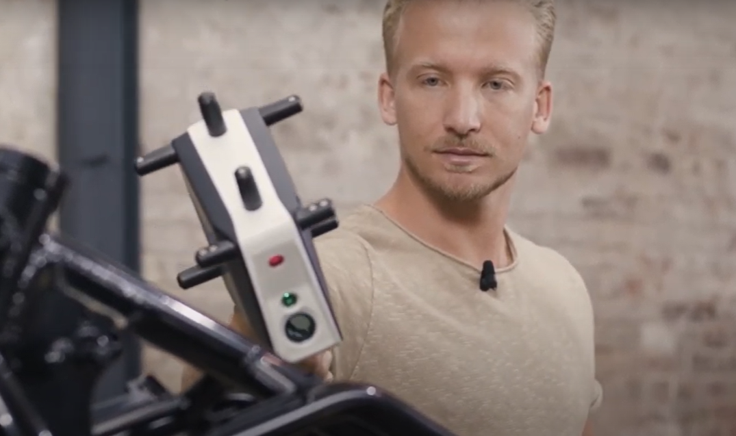
Scanning parts and inspecting them in GOM Inspect Pro has long been an integral part of Stahlotec’s process chain. They use the hand-held T-SCAN hawk to obtain 3D data. Keeping the usual scanning process and expanding the inspection options in the software to include automated inspection of the welds was therefore an obvious choice. This takes advantage of the fact that both entire parts and individual pieces of these parts, including their welds, can be scanned within seconds. This way, they are digitized and ready for evaluation as a 3D model in the GOM Inspect Pro inspection software.

t-scan_zeiss_3d-scanning

Visual testing of a motorcycle frame: the software in detail

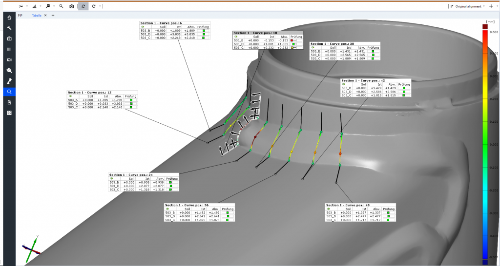
With the combination of the 3D scanning system and the Weld Check function in GOM Inspect Pro, automated visual testing is possible on any part regardless of size and shape. A motorcycle frame serves as an illustration in this example. After this has been measured with the hand-held T-SCAN hawk, the scan data is loaded into the GOM Inspect Pro software. This is followed by the actual inspection of the welds. A simple curve is used in the software to select the weld to be inspected. Then, any number of sections can be defined, e.g., all at a distance of 10 mm. These sections of the motorcycle frame can now be evaluated with the new additional function “Weld Check” (weld inspection). All characteristics of DIN standard 5817 are automatically stored there and are not only inspected at the click of a mouse, but also classified directly according to the corresponding rating categories B, C or D. With the help of a simple traffic light system, it is possible to see at a glance whether the rating categories are met. Green means fulfilled, orange indicates that it is just within the tolerance and red does not meet the criteria.
In our example, the selected weld does not meet the weld reinforcement specifications in only one section. Separate reports can already be created during the inspection of individual features. Of course, an overall reporting of all features of the VT is also possible. This enables a digital documentation of all conducted visual tests. If a reference has been stored in the software, the position and completeness of the welds can also be checked. This reference can be a CAD model or a 3D scan. Thus, for a small series of motorcycle frames, the sample scan could be saved as a template and used as a benchmark for series inspection.

Start now with the automated inspection of welds

If you are interested in getting started with automated weld inspection now or would like to find out more about 3D scanning systems simply contact support@handsonmetrology.com. You can also request a demo for the Weld Check Package here, which is available in the GOM Inspect Pro version.

What's your thoughts on this?

Discuss with us on LinkedIn

Join our mailing list

Be the first to know what's new

HOM_Video_Channel_QR_Code

Just a second!

Thank you for your interest. If you provide your contact info, we will inform you whenever a new episode of our Geek Talk is available.